6.18.2008

Circuit Magic

License : Shareware.

Circuit Magic is an electrical circuits simulation program specifically designed for students teaching basics electronics, electrical laws & circuit theory. Unlike many electronic circuit analyzers, Circuit Magic can analyze circuits like a man. Circuits are simulated step by step, using natural solving strategy.

With Circuit Magic's easy to use Schematics editor you can construct electrical circuit schematics consisting of direct and alternating currents devices such as resistors, capacitors, inductors, impedances, DC voltage sources, DC current sources, AC voltage sources, AC current sources.
Circuit Magic's advanced analysis capabilities, allow you to analyze basic electronic circuits using Kirchhoff's Laws, Node Voltage & Mesh Currents methods.


Download

If the above link does'nt work try this mirror link: [Download]

Source : circuit-magic.

EPE Magazine Index

License : Freeware.

A full index of all constructional projects published in Everyday Practical Electronics magazine is available to download. This is available as both a stand-alone application and an MS Access database. The stand-alone version includes the database file and can be used without having Access installed, and allows you to search for projects by description or date. It requires the .NET 2.0 framework; the installation program will check if you already have this installed and will download and install it if not.


Download

If the above link does'nt work try this mirror link: [Download]

Source : epemag.

Resistors Attack (game)

License : Freeware.

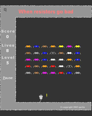
A game created by Dave Cutcher (author of Electronics for the Evil Genius) to teach resistor colour codes. To play move left and right using the arrow keys. 'Shoot' at the attacking resistor by pressing the number key corresponding to the resistor colour. For example to kill a yellow resistor move below it and press 4, for a red resistor press 2 . . .


Download

If the above link does'nt work try this mirror link: [Download]


Source : evilgenius.

5.18.2008

1 INR = 45 Dollars ???

Imagine if 1 Rupee= 45 $ ??

Here is an old imagination... but renewed now...

What happens if ONE INDIAN RUPEE = FORTY-FIVE AMERICAN DOLLARS !!!

There'll be tremendous improvement in the economy of India. India's exports will increase, imports will decrease ad ...

India becomes a super power as Economy is Power.

That is this. Yes. From today on,

"ONE INDIAN RUPEE = FORTY-FIVE AMERICAN DOLLARS"

Imagine... from then, this may happen...

SCENE 1

Venue : Microsoft Corporation, New York, US

Some s/w engineers are seeing Photos.

s/w engg 1 : What's that?

s/w engg 2 : Bob's photographs from India.

s/w engg 1 : WOW! Let me see. Which is this place?

s/w engg 3 : (Sees the photo) This is Ramanthapur, Hyderabad.

s/w engg 1 : WOW! And what is this? He's got an TVS 50 also.

s/w engg 2 : Let me see (sees). Sexy yaar. This guy enjoys life man...

s/w engg 3 : You know how much a TVS 50 costs? Nearly 200K. Say it in dollars...

s/w engg 2: Oops. We can't dream of such a thing here.

s/w engg 1 : Let's go to India & try for a job.

[Everybody excited.]

SCENE 2

Venue: Sun Microsystems, SanFrancisco, California, US

s/w engg 1: I'm with you man. My Visa is expected

anytime. Soon I will fly to India

s/w engg 2 : Ohhh... When is the party?

s/w engg 1: When I get it on hand.

s/w engg 2: Where will you be working?

s/w engg 1 : I'll be working in Madhapur.

s/w engg 2 : Oh! Madhapur. Great yaar. where'z it ...

s/w engg 1 : It is in Hyderabad.

s/w engg 3 : Exciting place yaar. Nice climate Not like California. You’ll love the weather yaar.One of my friends is in Jaipur,Rajasthan...He says it's the ultimate place to live in. Cool maan.

s/w engg 2 : Who is the client yaar?

s/w engg 1: You know Municipal Corporation of Hyderabad?

s/w engg 3 : Yeah. MCH. One of my friends is there in the Road Cleaning Division. Most challenging job yaar. People are working in the cutting edge of technology there.

s/w engg 1 : I'll be writing software for the accounts department of the GCU.

s/w engg 2: GCU? what it means...?

s/w engg 1 : that is Garbage Collecting Unit.

s/w engg 3 : : Great yaar. That's what I like about that country. You can get a job which requires all your skill. Not like here. See I'm writing software for the space shuttle remote control.I hate this.

s/w engg 1 : Don't worry guys. I'll give you my Hotmail id. You can send your resume to me and I'll forward it to the HRD.

[Everybody takes down his Hotmail id.]

SCENE 3

Venue: IBM, New York, US

(Conversation between a Male s/w engg. and Female s/w engg.)

Male : Hi!

Female: Hi. You know. I'm planning to settle in India soon.

Male : What??

Female : Yeah. My marriage will be here in America only. He is doing his B.Tech in Al-Habeeb College and he's coming here for a month. His study will be over in 2 months. He's already got a job in BEBO (Bharat Electricity Board). We planned to settle in Mehdipatnam itself... I'm also planning to work there. Let's see...

Male: Good luck... dont forget us & US...

SCENE 4

Venue: Intel Corp. US

s/w engg 1: Great news guys. Our George has got admission in the Al-Habeeb College in Hyd with scholarship for B.Tech ( EIE). A great new field yaar...

All are excited...

George : Got my Visa yesterday. It's all finalized now.

s/w engg 2 : Congrats yaar. So you are out of this country.

S/w engg 1 : B.Tech in Electronics And Instrumentation ...ohh...man, enjoy your life there?

s/w engg 2 : : Got full aid, eh?

George : Yeah. Got the UGC scholarship That will be 120 Rupees per Year. . . (sooo great)

s/w engg 1 : Great. Enjoy.

s/w engg 2 : (Thinking loud) Hmmm... 120 Indian Rupees ...! That means 120 * 45 = 5400 Dollars... with that amount I can buy a three bed-room flat & a Mercedes here...!!!

Bug Detector With Beep

Schematic


Parts

1. R1 ( 390 ohm, 5% )
2. R2 ( 390 ohm, 5% )
3. C1 ( 1000 uF, 10V )
4. C2 ( 1.5 uF, 10V )
5. C3 ( 3.9 nF )
6. C4 ( 20 pF, Trimmer )
7. C5 ( 10 nF / 0.01uF or 103 )
8. IC1, IC2 ( 7413 or 74LS13 )

Source: uoguelph

Birdie Doorbell Ringer

Shematic


Notes


P1 is of experimental value. Start with 220 Ohms or so and modify to suit your needs. The transistor is a general purpose kind and is not critical, almost any PNP type will work. L1 is a bell-transformer which is usually already present in the house. If you wish, you could use a battery instead of the bell transformer. Just hookup a 9-volt battery (or wall adapter)to points 'A' and 'B' (A=+) the diode (D1) is to protect the circuit from accidental polarity reversal and is optional, but required as a rectifier for use with the bell transformer.

T1 is a General Purpose PNP transistor and probably anything will work. L2 comes out of an old am transistor radio. They look like miniature transformers and are usually colored red or green. You have to fiddle with different transformers as the sound can vary depending on the value.

The loudspeaker is a 8 Ohm type and must be larger than 200milli-Watt. I used a 2Watt type, but anything over 0.2W will do. It really sounds like a bird and when you release the doorbell button the sound slowly fades away. I have used this circuit in my house for over 20 years and even build the "Birdie" for others. Although an old circuit, the experimentation and the final results still give a punch. . . .Have fun!


Source: uoguelph

5.16.2008

Electronic Stethoscope

Description:

U1a operates as a low-noise microphone preamp. Its gain is only about 3.9 because the high output impedance of the drain of the FET inside the electret microphone causes U1a s effective input resistor to be about 12.2K. C2 has a fairly high value in order to pass very low frequency (about 20 to 30Hz) heartbeat sounds.

U1b operates as a low-noise Sallen and Key, Butterworth low-pass-filter with a cutoff frequency of about 103Hz. R7 and R8 provide a gain of about 1.6 and allow the use of equal values for C3 and C4 but still producing a sharp Butterworth response. The rolloff rate is 12dB/octave. C3 and C4 can be reduced to 4.7nF to increase the cutoff frequency to 1KHz to hear respiratory or mechanical (automobile engine) sounds.

The U4 circuit is optional and has a gain of 71 to drive the bi-colour LED.

U5 is a 1/4W power amplifier IC with built-in biasing and inputs that are referred to ground. It has a gain of 20. It can drive any type of headphones including low impedance (8 ohms) ones.

Schematic


Parts


R1

1

10K 1/4W Resistor

R2

1

2.2K 1/4W Resistor

R3, R9

0

Not used

R4

1

47K 1/4W Resistor

R5, R6, R7

3

33K 1/4W Resistor

R8

1

56K 1/4W Resistor

R10

1

4.7K 1/4W Resistor

R11

1

2.2K to 10K audio-taper (logarithmic) volume control

R12

1

330K 1/4W Resistor

R13, R15, R16

3

1K 1/4W Resistor

R14

1

3.9 Ohm 1/4W Resistor

C1, C8

2

470uF/16V Electrolytic Capacitor

C2

1

4.7uF/16V Electrolytic Capacitor

C3, C4

3

0.047uF/50V Metalized plastic-film Capacitor

C5

1

0.1uF/50V Ceramic disc Capacitor

C6, C7

2

1000uF/16V Electrolytic Capacitor

U1

U2, U3

U4

U5

1

0

1

1

TL072 Low-noise, dual opamp

Not used

741 opamp

LM386 1/4W power amp

MIC

1

Two-wire Electret Microphone

J1

1

1/8" Stereo Headphones Jack

LED

1

Red/green 2-wire LED

Batt1, Batt2

2

9V Alkaline Battery

SW

1

2-pole, single throw Power Switch

Misc.

1

Stethoscope head or jar lid, Rubber Sleeve for microphone.


Assembly

Assemble the circuit using Veroboard (stripboard) or a PCB.

Use a shielded cable for the microphone as shown on the schematic.

Fasten the microphone to the stethoscope head with a rubber isolating sleeve or use a short piece of rubber tubing on its nipple. A thick jar lid can be used as a stethoscope head. The microphone must be spaced away from the skin but the stethoscope head must be pressed to the skin, sealing the microphone from background noises and avoiding acoustical feedback with your headphones.

The microphone/stethoscope head must not be moved while listening to heartbeats to avoid friction noises.

Protect your hearing. Keep the microphone away from your headphones to avoid acoustical feedback.

5.15.2008

How to Solder

The solder pen must touch and heat up both the pad and the wire.
The solder should be fed to the side opposite the pen, not to the pen itself.
It will simply melt when the surface it touches is hot enough.


Photobucket


Source : elxevilgenius.com

5.14.2008

Electronics Assistant

License : Freeware.

Electronics Assistant is a Windows program that performs electronics-related calculations. It includes a resistor colour code calculator, resistance, capacitance and power calculations and more. Details of calculations can be saved or printed. It provides all the functions found in the calculators section of this site and more in a stand-alone user friendly program.


Version 4.1 has now been released and includes the following new features:

  1. Updated user interface
  2. Extra calculators for inductance and frequency
  3. Calculation of nearest preferred resistor values with a choice of 5 series from E12 to E192
  4. Links to open Windows Calculator and up to 3 user-defined programs from Electronics Assistant
  5. Information panels can be toggled on or off to save space when not required
  6. Built-in automatic new version update check
  7. Various bug fixes and enhancements

Version 4.1 also fixes a number of errors found in version 4.0.


Download

If the above link does'nt work try this mirror link: [Download]


Source : electronics2000

4.29.2008

Home

Welcome to e-ckts!!!

E-ckts

This site contains lots of FREE electronic circuits (schematics) & do-it-yourself (DIY) circuit diagrams for hobbyists, students, professionals etc. covering a wide range of categories in electronics. There are also links to sites that offer hobby electronic kits and other electronics hobby related stuff. Use the menu on the right to browse different circuit/e-book categories.The schematics and printed circuit board patterns are GIF's, and may show up different on some browsers. You might want to save the images (especially the PC board patterns) to your hard drive, load them into a photo editor (Photoshop, Paint Shop Pro, The GIMP, etc.) and adjust the size before you transfer the pattern to a board. Printed circuit board patterns are available possible. This page is always under construction and there will be new additions from time to time. Some of these circuits were designed by me, most are not. Whenever possible I have tried to credit the author of a circuit but since many of these circuits are from my personal collection that I have gathered over a period of many years, this information is not always available.

E-books

Download unlimited eBooks for FREE – anytime! Find the help you need, the information you seek, or fun reading to enjoy. Take advantage of our complimentary service to read as much as you want, when you want.


Note: In order to extract the installation (.exe) files from the compressed (zip,rar) files downloaded from this website u need Winzip / Winrar or . . .Read more.

4.26.2008

The Liberty Guide to Linux


Are you tired of being a slave to Microsoft’s monopolistic hold? As Mark Taber puts it, "being forced into using rigid, poorly designed, overpriced and unstable, bloated software". And now Windows XP stops working and you have to beg for Microsoft’s permission to use software that you overpaid for.

In April 2000, U.S. District Judge Thomas Penfield Jackson ruled that Microsoft violated two sections of the 1890 Sherman Act. He concluded that Microsoft was a monopoly that used anti-competitive means to maintain its dominance in Intel-based operating systems.

"Give me freedom from product activation or give me Linux" - Stephen Bucaro

Don’t subject yourself to Microsoft’s "product activation" abuse. There is a better operating system available that costs nothing, and you have the freedom to use as many copies of it as you want without begging for anyone's permission. It’s time to start.


Photobucket

Network+ Certification Prep


It is very difficult for a recruiter or employer to evaluate whether an individual is competent computer technology professional because the technology is very complicated. For this reason the Computing Technology Industry Association (CompTIA) has defined specific skills and knowledge that a computer technology professional must have. This is a great advantage to employers because, if an individual meets the CompTIA standards, they can be confident that the individual is a competent computer technology professional.

CompTIA does not do any testing itself, it only specifies the skills and knowledge that a computer technology professional must have to competently perform the job. The testing is administered by independent testing organizations such as Sylvan Prometric. When an individual passes the required examination, CompTIA awards them certification. CompTIA does not provide any training materials to prepare for the examinations. Training and and exam preparation is provided by independent training organizations.

There are several different areas of certification. A+ Computer Technician was the first certification developed by CompTIA. Network+ defines specific skills and knowledge that a computer networking technician must have. It verifies that you have the knowledge to competently perform the computer networking technician job.

This ebook provides some training to prepare you for the Network+ certification exam. Holding CompTIA certification is a great advantage to a computer technology professional because it provides proof to employers that they competence required to perform the job. Certification can help you acquire employment in the computer technology profession. In fact many employers require CompTIA certification.

If you are already working in the computer technology field, certification can help you advance and earn a higher salary. Being CompTIA certified can give you the self confidence and recognition you need to compete in today’s demanding job market.


Photobucket

Use the Windows Scripting Host to Master Your Computer


In the early days of computers, PC system administrators performed their tasks by typing DOS commands. They also wrote scripts, called "batch files", to perform system administration tasks. In 1995 Microsoft, embarrassed that DOS was a 16-bit single-tasking operating system, moved away from the command shell as a means to administer Windows.

While Unix and Linux system administrators have had a powerful command line environment that gave them powerful administrative capabilities well beyond that of a Windows system administrator, Windows system administrators had to use a convoluted combination of "Microsoft Management Consoles", Control Panel utilities, and "wizards" to perform tasks.

With Windows 2000 and higher, Microsoft included a program called "Windows Scripting Host" (WSH) that allows scripts to be run on Windows outside of a webpage. In effect, DOS batch files have returned, except scripts are multi-tasking and have a lot more power.

An administrator no longer has to waste time searching for the proper dialog box to perform a simple administrative task. Instead they can do the job with a handy little script from their script library.

This ebook is designed to give you an introduction to scripts and the Windows Scripting Host. It will get you started writing your own scripts. It contains many hands-on examples and provides you with a library of scripts to get you started.


Photobucket

Win 2000 Administrators Guide


Windows 2000 is Microsoft's latest version of the NT (New Technology) client-sever operating system. The Windows 2000 operating system is very complex and difficult to learn. The best way to learn is to set up your own training network. A minimal training network should have a Windows 2000 server and two Windows 2000 professional workstations. You also need the minimal components to network the computers.

This ebook assumes that you have basic familiarity with the Windows operating system. It shows you how to install, configure, and administrate a Windows 2000 network using a hands-on method.


Photobucket

Make Your Computer More Friendly


Do you often feel that you are involved in hand-to-hand combat with your computer? Did you think computers where designed to serve mankind, not fight back every time you want it to do something? This ebook shows you how to configure Windows so that your work will be much easier and faster.

There has been no SIGNIFICANT technological advance in Windows since Windows 95 (and I could make a case that there has been no significant technological advance in Windows since Windows 3.0). But in order to trick people into paying for "upgrades" Microsoft has made cosmetic changes and added trivial features that add to Windows bloat and waste memory and processing time.

The problem is that Windows default installation is configured to show off all the trivial bells and whistles that Microsoft's bored programmers have put in the software, while at the same time hiding some important information from you because they think you're too stupid to see it. If you are not an experienced user, or if you've just become accustomed to Microsoft's default configuration, you are working with an operating system configured for low productivity.

Fortunately you still have the ability to configure Windows to the way it was before most of the trivial features, excessive complexity and productivity tapping bloat was added. Once you do that, your work will be much easier and faster.


Photobucket

How to Configure and Maintain Your PC


Microsoft Windows is a very complicated operating system. Unfortunately, over the years, Windows upgrades have consisted of little more than added unnecessary trivia (like the search puppy) and complexity (like the registry).

When you first install Windows, it is NOT configured for optimal performance. Instead it’s configured to display all the unnecessary bells and whistles that hog your computers processor and memory causing your system to run slow.

This ebook shows you how to take control of your computer and configure it the way it should be, for optimal performance. Then this ebook show you how to perform critical computer maintenance such as backing up, defragmenting the hard disk, setting up anti-virus, anti-spyware, and firewall protection systems.

Then, because the longer Windows runs, the more corrupt and degraded it becomes, this ebook shows you how to perform the inevitable task of reloading Windows.


Photobucket

PC Technician's Toolkit


Unfortunately, a PC Running Microsoft Windows is about as reliable as a 75 Gremlin. Although it's probably easier and cheaper to fix the Gremlin. For repairs, you could take your PC back to the place you purchased it - if you never want to see it again. Or maybe you could take it to an independent shop where they charge you $100.00 just to set it on the bench, and then charge you another $200.00 to replace the hard drive (the actual problem was a loose connector).

The wise thing to do would be to learn how to maintain and repair your own PC. That's what this ebook is all about. You'll learn about Your PC, from computer thermodynamics to plug and play resource allocation. How to maintain your computer, from defragmenting your hard disk to working with the registry. How to secure your computer, from user permissions to spyware blocking firewalls. How to troubleshoot your PC, from taking too long to start to bringing a totally dead computer back to life.

How do I know all this? I have been a computer hobbyist since about 1981. My first computer was a Commodore Vic 20. The first computer that I built myself was an IBM XT clone. The operating system I used was DOS version 2. I have built many PC's since then. I have probably tossed out more obsolete computer hardware and software than most people have seen in their lifetime.

This ebook also provides you with many important resources. Sources for free technical information. Sources for freeware and shareware PC diagnostic software. Web sites that give you free technical assistance. With these resourses you could start your own PC repair shop and charge $100.00 an hour!

I don't get many Opportunities to fix PC's now days, because whenever I start walking toward one that's acting up - it starts working again - all by itself. Especially if I have a screwdriver in my hand. So go ahead and read through this ebook. Someday you too will have your PC trained to obey.


Photobucket

Build your own PC


Why would you want to build your own computer? Not to save money. With a decent manufactured computer costing less than $400.00, it will cost you more to buy the parts to build your own. There are five advantages to building rather than buying.

1. Most manufactured computers are build using proprietary components. When (not if) your computer breaks down, you can’t use off-the-shelf replacement parts. You have to pay a lot more for the manufacturers proprietary replacement parts.

2. Low-cost manufactured computers use the cheapest components. These components are marginal or below specifications. When you build your own computer, you select the quality of each component.

3. When you have built your own computer, you are more knowledgeable and capable of performing your own troubleshooting. You don’t have to pay $75.00 per hour for a service technician.

4. When your computer becomes outdated, you can easily upgrade it yourself. You will be a better judge of when it’s more logical to build a new computer from scratch, or to update the old one.

5. You will feel the pride and confidence of having built your own computer. And, you will have proof that you really are smarter than your friends!

Yes, you can build your own computer. Today’s plug-and-play motherboards with onboard video, sound, and network circuitry make it easy. This highly illustrated ebook shows you how to build your own computer in 30 minutes (plus an hour of waiting while installing the operating system).


Photobucket

Basic PC Anatomy


Everything else in life is just a game we play." Computers are a part of that game, a toy that everybody takes way too serious. If you don't understand computers, if you're not up on the latest computer lingo, you're considered illiterate. This ebook can help.

Maybe you want to build your own computer, or maybe you want to fix the computer you already have. Before you tackle those jobs you might first want to first learn the basic structure and operation of computers. This ebook can help.

Most basic computer books drag you through the entire history of computers, wasting your time learning about interfaces and hardware that haven't been seen in decades. Or they use pictures with large brightly colored areas like you're a preschooler. Or they load the book up with filler like you're a dummy or an idiot.

This ebook explains the main components and functions of a computer in an efficient and concise manor without taking you down memory lane or wasting your time with witty filler material. When you finish reading it, you'll understand enough about computers to no longer be considered illiterate, and you'll still have time left to go fishing.


Photobucket

4.25.2008

22 Watt Audio Amplifier

The 22 watt amp is easy to build, and very inexpensive. The circuit can be used as a booster in a car audio system, an amp for satellite speakers in a surround sound or home theater system, or as an amp for computer speakers. The circuit is quite compact and uses only about 60 watts.

Schematic


Parts

1. R1 (
39K 1/4 Watt Resistor).
2. C1, C2 (10uf 25V Electrolytic Capacitor).
3. C3 (100uf 25V Electrolytic Capacitor).
4. C4 (
47uf 25V Electrolytic Capacitor).
5. C5 (0.1uf 25V Ceramic Capacitor).
6. C6 (2200uf 25V Electrolytic Capacitor).
7. U1 (TDA1554 Two Channel Audio Amp Chip).
8. Misc (Heatsink For U1, Binding Posts for Output, RCA Jacks for Input, Wire, Board).

Notes

The circuit works best with 4 ohm speakers, but 8 ohm units will do.

The circuit dissipates roughly 28 watts of heat, so a good heatsink is necessary. The chip should run cool enough to touch with the proper heatsink installed.

The circuit operates at 12 Volts at about 5 Amps at full volume. Lower volumes use less current, and therefore produce less heat.

Printed circuit board is preferred, but universal solder or perf board will do. Keep lead length short.

4.23.2008

Electronic Scoring Game

You can play this game alone or with your friends. The circuit comprises a timer IC, two decade counters and a display driver along with a 7-segment display. The game is simple. As stated above, it is a scoring game and the competitor who scores 100 points rapidly (in short steps) is the winner. For scoring, one has the option of pressing either switch S2 or S3. Switch S2, when pressed, makes the counter count in the forward direction, while switch S3 helps to count downwards. Before starting a fresh game, and for that matter even a fresh move, you must press switch S1 to reset the circuit. Thereafter, press any of the two switches, i.e. S2 or S3. On pressing switch S2 or S3, the counter’s BCD outputs change very rapidly and when you release the switch, the last number remains latched at the output of IC2. The latched BCD number is input to BCD to 7-segment decoder/driver IC3 which drives a common-anode display DIS1. However, you can read this number only when you press switch S4.

The sequence of operations for playing the game between, say two players ‘X’ and ‘Y’, is summarised below:

1. Player ‘X’ starts by momentary pressing of reset switch S1 followed by pressing and releasing of either switch S2 or S3. Thereafter he presses switch S4 to read the display (score) and notes down this number (say X1) manually.

2. Player ‘Y’ also starts by momentary pressing of switch S1 followed by pressing of switch S2 or S3 and then notes down his score (say Y1), after pressing switch S4, exactly in the same fashion as done by the first player.

3. Player ‘X’ again presses switch S1 and repeats the steps shown in step 1 above and notes down his new score (say, X2). He adds up this score to his previous score. The same procedure is repeated by player ‘Y’ in his turn.

4. The game carries on until the score attained by one of the two players totals up to or exceeds 100, to be declared as the winner.

Several players can participate in this game, with each getting a chance to score during his own turn. The assembly can be done using a multipurpose board. Fix the display (LEDs and 7-segment display) on top of the cabinet along with the three switches. The supply voltage for the circuit is 5V.

Schematic


Link Exchange

Hi friends,

If you own any blog or website n r interested in exchanging links with me, then;

1. Send your request (with banners and links) to my mail.

2. Add any 1 of 2 banners given below to your website/blog (just copy and paste the html code given in the box under each banner), after adding leave a comment.

3. I'll add a link back to you as soon as possible.


Electronic Circuits


Electronic Circuits


(thanks)

Submit your circuit

Got a circuit?
Then e-mail it to hashmi.theheartsmuggler@gmail.com (please put "Circuit Submit" as the subject).

The submission should include the following:

  1. The circuit diagram (in jpeg/gif format only)
  2. What the circuit does.
  3. Brief description of the circuit. (optional)
  4. Your Name & E-mail

(thanks).

4.22.2008

AM Transmitter

In this circuit, a 74HC14 hex Schmitt trigger inverter is used as a square wave oscillator to drive a small signal transistor in a Class C amplifier configuration. The oscillator frequency can be either fixed by a crystal or made adjustable (VFO) with a capacitor/resistor combination.

Schematic

Notes

This ircuit is deliberately limited in power output but will provide amplitude modulation (AM) of voice over the medium wave band.
The circuit is in two halfs, an audio amplifier and an RF oscillator. The oscillator is built around Q1 and associated components. The tank circuit L1 and VC1 is tunable from about 500kHz to 1600KHz. These components can be used from an old MW radio, if available. Q1 needs regenerative feedback to oscillate and this is achieved by connecting the base and collector of Q1 to opposite ends of the tank circuit. The 1nF capacitor C7, couples signals from the base to the top of L1, and C2, 100pF ensures that the oscillation is passed from collector, to the emitter, and via the internal base emitter resistance of the transistor, back to the base again. Resistor R2 has an important role in this circuit. It ensures that the oscillation will not be shunted to ground via the very low internal emitter resistance, re of Q1, and also increases the input impedance so that the modulation signal will not be shunted. Oscillation frequency is adjusted with VC1.
Q2 is wired as a common emitter amplifier, C5 decoupling the emitter resistor and realising full gain of this stage. The microphone is an electret condenser mic and the amount of AM modulation is adjusted with the 4.7k preset resistor P1.
An antenna is not needed, but 30cm of wire may be used at the collector to increase transmitter range.


Disclaimer

www.e-ckts.co.nr a collection of links to many electronic circuits or schematics which serves as a vital resource for engineers, hobbyists& inventors, the site's collection of information will help you find quick solutions to electronic design problems. As I've not tested all these electronic circuits, I cannot attest to their accuracy; therefore, I do not provide a warranty of any kind and cannot be held responsible in any manner.


Thank You.

FM Transmitter

Here is the schematic, PC board pattern, and parts placement for a low powered FM transmitter. The range of the transmitter when running at 9V is about 300 feet. Running it from 12V increases the range to about 400 feet. This transmitter should not be used as a room or telephone bug.

Schematic
Parts

1. C1 (0.001uf Disc Capacitor).
2. C2 (5.6pf Disc Capacitor).
3. C3, C4 (10uf Electrolytic Capacitor).
4. C5 (3-18pf Adjustable Cap).
5. R1 (270 Ohm 1/8W or 1/4W Resistor).
6. R2, R5, R6 (4.7k 1/8W or 1/4W Resistor).
7. R3 (10k 1/8W
or 1/4W Resistor).
8. R4 (100k 1/8W
or 1/4W Resistor).
9. Q1, Q2 (2N2222A NPN Transistor or 2N3904, NTE123A).
10. L1, L2 (5 Turn Air Core Coil).
11. Mic (Electret Microphone).
12. Misc (9V Battery Snap, PC Board, Wire For Antenna).

Notes

L1 and L2 are 5 turns of 28 AWG enamel coated magnet wire wound with a inside diameter of about 4mm. The inside of a ballpoint pen works well (the plastic tube that holds the ink). Remove the form after winding then install the coil on the circuit board, being careful not to bend it.

C5 is used for tuning. This transmitter operates on the normal broadcast frequencies (88-108MHz).

Q1 and Q2 can also be 2N3904 or something similar.

You can use 1/4 W resistors mounted vertically instead of 1/8 W resistors.

You may want to bypass the battery with a .01uf capacitor.

An antenna may not be required for operation.

FM Telephone Bug

Here is a simple transmitter that when connected to a phone line, will transmit anything on that line (execpt the dial tone) to any FM radio. The frequency can be tuned from 88 to about 94Mhz and the range is about 200 feet. It is extremely easy to build and is therefore a good, useful beginner project.

Schematic


Parts

1. R1 (180 Ohm 1/4 W Resistor).
2. R2 (12K 1/4 W Resistor).
3. C1 (330pF Capacitor).
4. C2 (12pF Capacitor).
5. C3 (471pF Capacitor).
6. C4 (22pF Capacitor).
7. Q1 (2SA933 Transistor)
8. D1, D2, D3, D4 (1SS119 Silicon Diode).
9. D5 (Red LED).
10. S1 (SPDT Switch).
11. L1 (Tuning Coil).
12. Misc (Wire, Circuit Board).

Notes

L1 is 7 turns of 22 AWG wire wound on a 9/64 drill bit. You may need to experiment with the number of turns.

By stretching and compressing the coils of L1, you can change the frequency of the transmitter. The min frequency is about 88 Mhz, while the max frequency is around 94 Mhz.

The green wire from the phone line goes to IN1. The red wire from the phone line goes to IN2. The green wire from OUT1 goes to the phone(s), as well as the red wire from OUT2.

The antenna is a piece of thin (22 AWG) wire about 5 inches long.

All capacitors are rated for 250V or greater.

The transmitter is powered by the phone line and is on only when the phone is in use. S1 can be used to turn the transmitter off if it is not needed.

If you have problems with the LED burning out, then add a 300 ohm 1/4W resistor in series with it.

Cut Phone Line Detector

When the circuit detects that a phone line has been cut, it activates a MOSFET which can be used to drive a relay, motor, etc. It can also be connected to a security system.

Schematic


Parts

1. R1, R2, R3 (22 M 1/4 W Resistor).
2. R4 (2.2 M 1/4 W Resistor).
3. C1 (0.47uF 250V Mylar Capicitor).
4. Q1 (2N3904 or 2N2222 Transistor).
5. Q2 (2N3906 Transistor).
6. Q3 (IRF510 Power MOSFET).
7. D1 (1N914 Diode).
8. Load (see notes).
9. Misc (Wire, Phone Connectors, PCB).

Notes

The "Load" can be a relay, lamp, motor, etc. The circuit can also be connected to a security system to sound an alarm in case the phone line is cut.

If the circuit is connected to a security system or other circuit, both circuits must be electrically isolated from each other using an opto-isolator, relay, etc. This also means that the Cut Phone Line Detector must be powered by a seperate 9V supply.