6.18.2008

Circuit Magic

License : Shareware.

Circuit Magic is an electrical circuits simulation program specifically designed for students teaching basics electronics, electrical laws & circuit theory. Unlike many electronic circuit analyzers, Circuit Magic can analyze circuits like a man. Circuits are simulated step by step, using natural solving strategy.

With Circuit Magic's easy to use Schematics editor you can construct electrical circuit schematics consisting of direct and alternating currents devices such as resistors, capacitors, inductors, impedances, DC voltage sources, DC current sources, AC voltage sources, AC current sources.
Circuit Magic's advanced analysis capabilities, allow you to analyze basic electronic circuits using Kirchhoff's Laws, Node Voltage & Mesh Currents methods.


Download

If the above link does'nt work try this mirror link: [Download]

Source : circuit-magic.

EPE Magazine Index

License : Freeware.

A full index of all constructional projects published in Everyday Practical Electronics magazine is available to download. This is available as both a stand-alone application and an MS Access database. The stand-alone version includes the database file and can be used without having Access installed, and allows you to search for projects by description or date. It requires the .NET 2.0 framework; the installation program will check if you already have this installed and will download and install it if not.


Download

If the above link does'nt work try this mirror link: [Download]

Source : epemag.

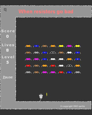
Resistors Attack (game)

License : Freeware.

A game created by Dave Cutcher (author of Electronics for the Evil Genius) to teach resistor colour codes. To play move left and right using the arrow keys. 'Shoot' at the attacking resistor by pressing the number key corresponding to the resistor colour. For example to kill a yellow resistor move below it and press 4, for a red resistor press 2 . . .


Download

If the above link does'nt work try this mirror link: [Download]


Source : evilgenius.

5.18.2008

1 INR = 45 Dollars ???

Imagine if 1 Rupee= 45 $ ??

Here is an old imagination... but renewed now...

What happens if ONE INDIAN RUPEE = FORTY-FIVE AMERICAN DOLLARS !!!

There'll be tremendous improvement in the economy of India. India's exports will increase, imports will decrease ad ...

India becomes a super power as Economy is Power.

That is this. Yes. From today on,

"ONE INDIAN RUPEE = FORTY-FIVE AMERICAN DOLLARS"

Imagine... from then, this may happen...

SCENE 1

Venue : Microsoft Corporation, New York, US

Some s/w engineers are seeing Photos.

s/w engg 1 : What's that?

s/w engg 2 : Bob's photographs from India.

s/w engg 1 : WOW! Let me see. Which is this place?

s/w engg 3 : (Sees the photo) This is Ramanthapur, Hyderabad.

s/w engg 1 : WOW! And what is this? He's got an TVS 50 also.

s/w engg 2 : Let me see (sees). Sexy yaar. This guy enjoys life man...

s/w engg 3 : You know how much a TVS 50 costs? Nearly 200K. Say it in dollars...

s/w engg 2: Oops. We can't dream of such a thing here.

s/w engg 1 : Let's go to India & try for a job.

[Everybody excited.]

SCENE 2

Venue: Sun Microsystems, SanFrancisco, California, US

s/w engg 1: I'm with you man. My Visa is expected

anytime. Soon I will fly to India

s/w engg 2 : Ohhh... When is the party?

s/w engg 1: When I get it on hand.

s/w engg 2: Where will you be working?

s/w engg 1 : I'll be working in Madhapur.

s/w engg 2 : Oh! Madhapur. Great yaar. where'z it ...

s/w engg 1 : It is in Hyderabad.

s/w engg 3 : Exciting place yaar. Nice climate Not like California. You’ll love the weather yaar.One of my friends is in Jaipur,Rajasthan...He says it's the ultimate place to live in. Cool maan.

s/w engg 2 : Who is the client yaar?

s/w engg 1: You know Municipal Corporation of Hyderabad?

s/w engg 3 : Yeah. MCH. One of my friends is there in the Road Cleaning Division. Most challenging job yaar. People are working in the cutting edge of technology there.

s/w engg 1 : I'll be writing software for the accounts department of the GCU.

s/w engg 2: GCU? what it means...?

s/w engg 1 : that is Garbage Collecting Unit.

s/w engg 3 : : Great yaar. That's what I like about that country. You can get a job which requires all your skill. Not like here. See I'm writing software for the space shuttle remote control.I hate this.

s/w engg 1 : Don't worry guys. I'll give you my Hotmail id. You can send your resume to me and I'll forward it to the HRD.

[Everybody takes down his Hotmail id.]

SCENE 3

Venue: IBM, New York, US

(Conversation between a Male s/w engg. and Female s/w engg.)

Male : Hi!

Female: Hi. You know. I'm planning to settle in India soon.

Male : What??

Female : Yeah. My marriage will be here in America only. He is doing his B.Tech in Al-Habeeb College and he's coming here for a month. His study will be over in 2 months. He's already got a job in BEBO (Bharat Electricity Board). We planned to settle in Mehdipatnam itself... I'm also planning to work there. Let's see...

Male: Good luck... dont forget us & US...

SCENE 4

Venue: Intel Corp. US

s/w engg 1: Great news guys. Our George has got admission in the Al-Habeeb College in Hyd with scholarship for B.Tech ( EIE). A great new field yaar...

All are excited...

George : Got my Visa yesterday. It's all finalized now.

s/w engg 2 : Congrats yaar. So you are out of this country.

S/w engg 1 : B.Tech in Electronics And Instrumentation ...ohh...man, enjoy your life there?

s/w engg 2 : : Got full aid, eh?

George : Yeah. Got the UGC scholarship That will be 120 Rupees per Year. . . (sooo great)

s/w engg 1 : Great. Enjoy.

s/w engg 2 : (Thinking loud) Hmmm... 120 Indian Rupees ...! That means 120 * 45 = 5400 Dollars... with that amount I can buy a three bed-room flat & a Mercedes here...!!!

Bug Detector With Beep

Schematic


Parts

1. R1 ( 390 ohm, 5% )
2. R2 ( 390 ohm, 5% )
3. C1 ( 1000 uF, 10V )
4. C2 ( 1.5 uF, 10V )
5. C3 ( 3.9 nF )
6. C4 ( 20 pF, Trimmer )
7. C5 ( 10 nF / 0.01uF or 103 )
8. IC1, IC2 ( 7413 or 74LS13 )

Source: uoguelph

Birdie Doorbell Ringer

Shematic


Notes


P1 is of experimental value. Start with 220 Ohms or so and modify to suit your needs. The transistor is a general purpose kind and is not critical, almost any PNP type will work. L1 is a bell-transformer which is usually already present in the house. If you wish, you could use a battery instead of the bell transformer. Just hookup a 9-volt battery (or wall adapter)to points 'A' and 'B' (A=+) the diode (D1) is to protect the circuit from accidental polarity reversal and is optional, but required as a rectifier for use with the bell transformer.

T1 is a General Purpose PNP transistor and probably anything will work. L2 comes out of an old am transistor radio. They look like miniature transformers and are usually colored red or green. You have to fiddle with different transformers as the sound can vary depending on the value.

The loudspeaker is a 8 Ohm type and must be larger than 200milli-Watt. I used a 2Watt type, but anything over 0.2W will do. It really sounds like a bird and when you release the doorbell button the sound slowly fades away. I have used this circuit in my house for over 20 years and even build the "Birdie" for others. Although an old circuit, the experimentation and the final results still give a punch. . . .Have fun!


Source: uoguelph

5.16.2008

Electronic Stethoscope

Description:

U1a operates as a low-noise microphone preamp. Its gain is only about 3.9 because the high output impedance of the drain of the FET inside the electret microphone causes U1a s effective input resistor to be about 12.2K. C2 has a fairly high value in order to pass very low frequency (about 20 to 30Hz) heartbeat sounds.

U1b operates as a low-noise Sallen and Key, Butterworth low-pass-filter with a cutoff frequency of about 103Hz. R7 and R8 provide a gain of about 1.6 and allow the use of equal values for C3 and C4 but still producing a sharp Butterworth response. The rolloff rate is 12dB/octave. C3 and C4 can be reduced to 4.7nF to increase the cutoff frequency to 1KHz to hear respiratory or mechanical (automobile engine) sounds.

The U4 circuit is optional and has a gain of 71 to drive the bi-colour LED.

U5 is a 1/4W power amplifier IC with built-in biasing and inputs that are referred to ground. It has a gain of 20. It can drive any type of headphones including low impedance (8 ohms) ones.

Schematic


Parts


R1

1

10K 1/4W Resistor

R2

1

2.2K 1/4W Resistor

R3, R9

0

Not used

R4

1

47K 1/4W Resistor

R5, R6, R7

3

33K 1/4W Resistor

R8

1

56K 1/4W Resistor

R10

1

4.7K 1/4W Resistor

R11

1

2.2K to 10K audio-taper (logarithmic) volume control

R12

1

330K 1/4W Resistor

R13, R15, R16

3

1K 1/4W Resistor

R14

1

3.9 Ohm 1/4W Resistor

C1, C8

2

470uF/16V Electrolytic Capacitor

C2

1

4.7uF/16V Electrolytic Capacitor

C3, C4

3

0.047uF/50V Metalized plastic-film Capacitor

C5

1

0.1uF/50V Ceramic disc Capacitor

C6, C7

2

1000uF/16V Electrolytic Capacitor

U1

U2, U3

U4

U5

1

0

1

1

TL072 Low-noise, dual opamp

Not used

741 opamp

LM386 1/4W power amp

MIC

1

Two-wire Electret Microphone

J1

1

1/8" Stereo Headphones Jack

LED

1

Red/green 2-wire LED

Batt1, Batt2

2

9V Alkaline Battery

SW

1

2-pole, single throw Power Switch

Misc.

1

Stethoscope head or jar lid, Rubber Sleeve for microphone.


Assembly

Assemble the circuit using Veroboard (stripboard) or a PCB.

Use a shielded cable for the microphone as shown on the schematic.

Fasten the microphone to the stethoscope head with a rubber isolating sleeve or use a short piece of rubber tubing on its nipple. A thick jar lid can be used as a stethoscope head. The microphone must be spaced away from the skin but the stethoscope head must be pressed to the skin, sealing the microphone from background noises and avoiding acoustical feedback with your headphones.

The microphone/stethoscope head must not be moved while listening to heartbeats to avoid friction noises.

Protect your hearing. Keep the microphone away from your headphones to avoid acoustical feedback.

5.15.2008

How to Solder

The solder pen must touch and heat up both the pad and the wire.
The solder should be fed to the side opposite the pen, not to the pen itself.
It will simply melt when the surface it touches is hot enough.


Photobucket


Source : elxevilgenius.com

5.14.2008

Electronics Assistant

License : Freeware.

Electronics Assistant is a Windows program that performs electronics-related calculations. It includes a resistor colour code calculator, resistance, capacitance and power calculations and more. Details of calculations can be saved or printed. It provides all the functions found in the calculators section of this site and more in a stand-alone user friendly program.


Version 4.1 has now been released and includes the following new features:

  1. Updated user interface
  2. Extra calculators for inductance and frequency
  3. Calculation of nearest preferred resistor values with a choice of 5 series from E12 to E192
  4. Links to open Windows Calculator and up to 3 user-defined programs from Electronics Assistant
  5. Information panels can be toggled on or off to save space when not required
  6. Built-in automatic new version update check
  7. Various bug fixes and enhancements

Version 4.1 also fixes a number of errors found in version 4.0.


Download

If the above link does'nt work try this mirror link: [Download]


Source : electronics2000

4.29.2008

Home

Welcome to e-ckts!!!

E-ckts

This site contains lots of FREE electronic circuits (schematics) & do-it-yourself (DIY) circuit diagrams for hobbyists, students, professionals etc. covering a wide range of categories in electronics. There are also links to sites that offer hobby electronic kits and other electronics hobby related stuff. Use the menu on the right to browse different circuit/e-book categories.The schematics and printed circuit board patterns are GIF's, and may show up different on some browsers. You might want to save the images (especially the PC board patterns) to your hard drive, load them into a photo editor (Photoshop, Paint Shop Pro, The GIMP, etc.) and adjust the size before you transfer the pattern to a board. Printed circuit board patterns are available possible. This page is always under construction and there will be new additions from time to time. Some of these circuits were designed by me, most are not. Whenever possible I have tried to credit the author of a circuit but since many of these circuits are from my personal collection that I have gathered over a period of many years, this information is not always available.

E-books

Download unlimited eBooks for FREE – anytime! Find the help you need, the information you seek, or fun reading to enjoy. Take advantage of our complimentary service to read as much as you want, when you want.


Note: In order to extract the installation (.exe) files from the compressed (zip,rar) files downloaded from this website u need Winzip / Winrar or . . .Read more.